Making some change to specification before release…
Disclaimer
Products are developed from extension of my hobby, and little amount is hand-made and sold for other hobbyists.
Since they are hand-made by me, there may be initial failure, poor quality in soldering, lack of quality in design, etc. Recommended to use for hobby purpose
Please read and understand specification of this product, and test before using. I will hold no responsibility for any damage or harm caused by the use of this product.
Description
Useful tool based on ESP32 for developing ATMega328 microcomputer such as Arduino UNO, Nano. Have following features.
- Write / fix Bootloader
- Fuse
- Check setting
- Set fuse (bootloader enable/disable, read only, clear)
- Arduino as ISP (avrdude via USB)
- avrdude via WiFi
- Burn hex file (compiled sketch/bootloader) stored in microSD
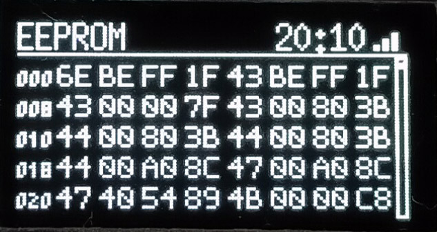
- EEPROM
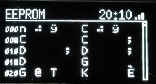
- Read and view (HEX / ASCII format)
- Save data to microSD
- Clear
- Write EEPROM data saved to microSD
- View EEPROM data saved to microSD
- Serial monitor
- View text
- View simple graph
- Save data to microSD
- View text file stored in microSD
- WiFi
- AP / STA mode, off
- Sync with NTP server (file timestamp)
- Configure WiFi connection from smartphone
- HTTP server (Access from PC / phone browser)
- File list in microSD
- Download file in microSD
- Upload file to microSD
- Delete file from microSD
Many useful functions such as configure or write bootloader, burn hex file saved in microSD, check data in EEPROM, serial monitor debugging.
Files can be transferred to / from microSD via WiFi using smartphone, so for example, you can fetch EEPROM data from chip to microSD, then transfer to smartphone, attach to mail and send (AP mode will connect tool and smartphone directly).
Power can be supplied from USB connector on tool, or can be supplied from target board.
Other usage can be considered, such as modify tool program source (preparing) to view serial monitor or EEPROM data in customized format, change value every time writing to EEPROM for assigning unique ID per chip.
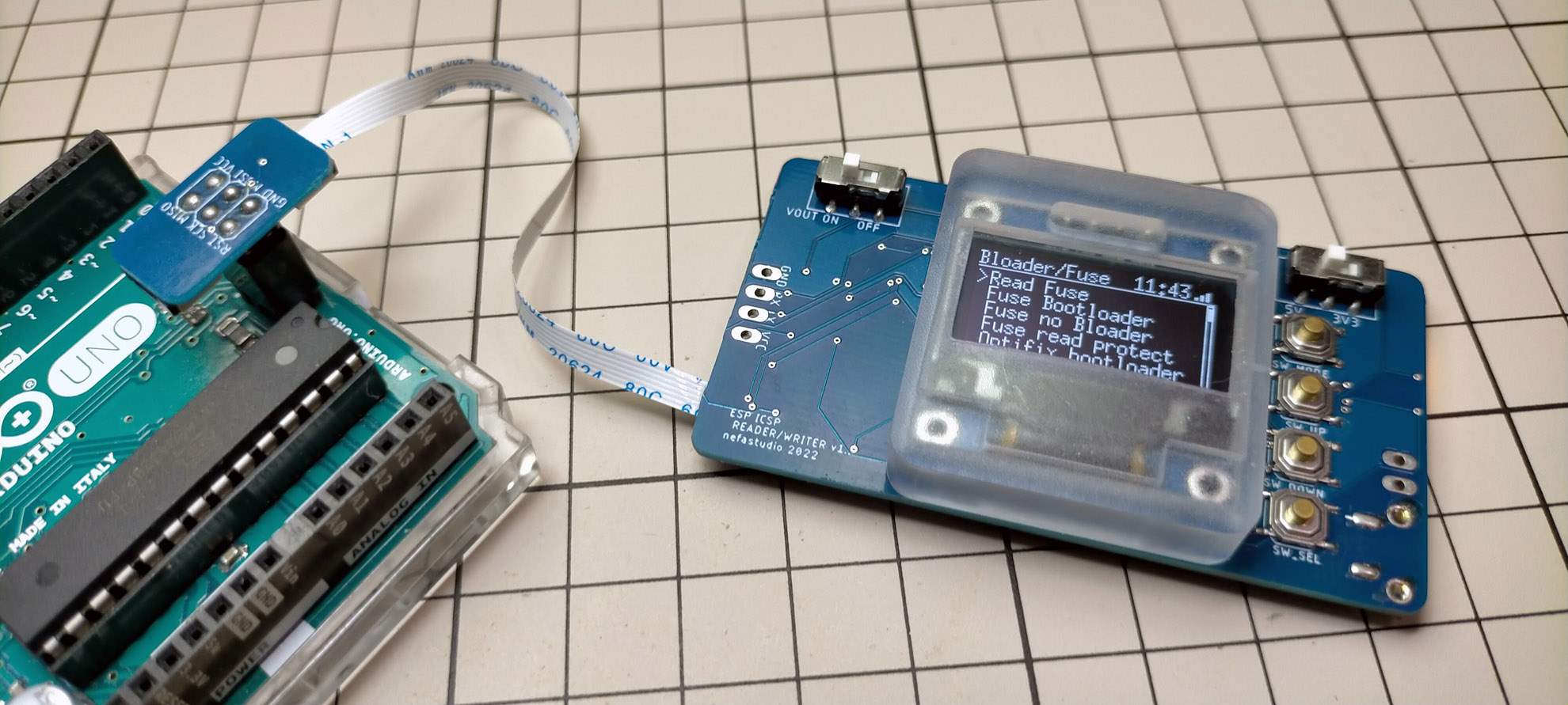
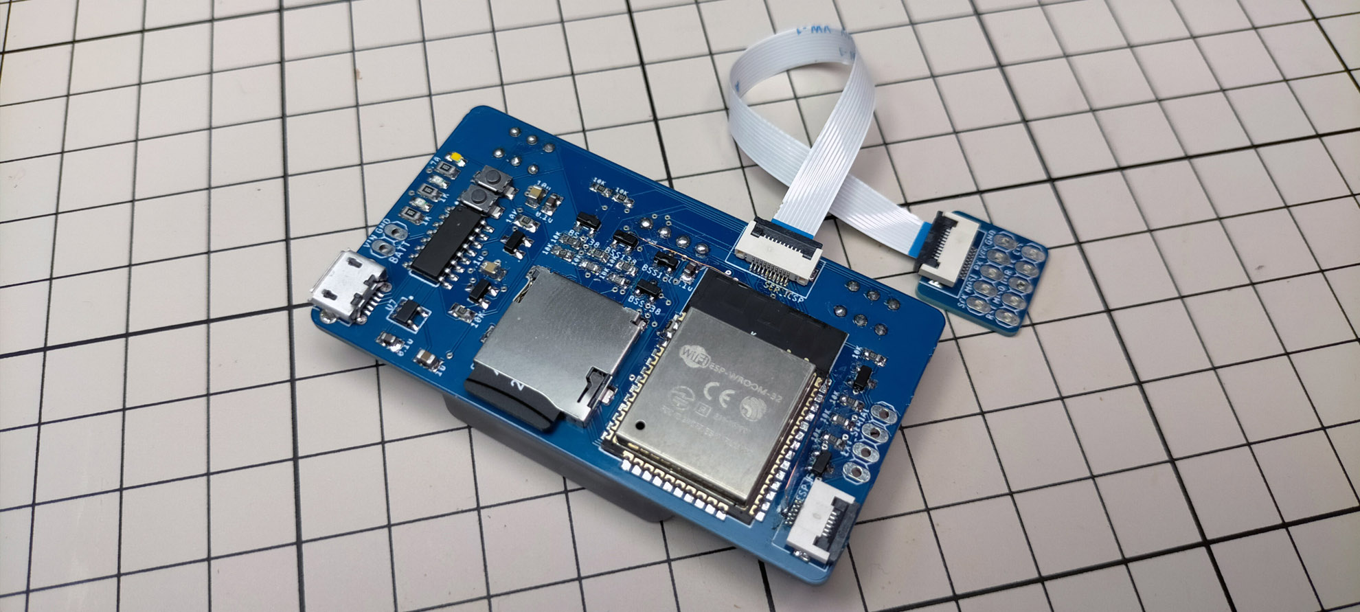
Included items
Below parts are included. Display cover is 3D printed and fixed with double sided tape.
Used parts may differ for improvement or availability of electronic parts.
- Tool device
- 6cm 6pin flexible flat cable
- 10cm 6pin flexible flat cable
- 10cm 10pin flexible flat cable
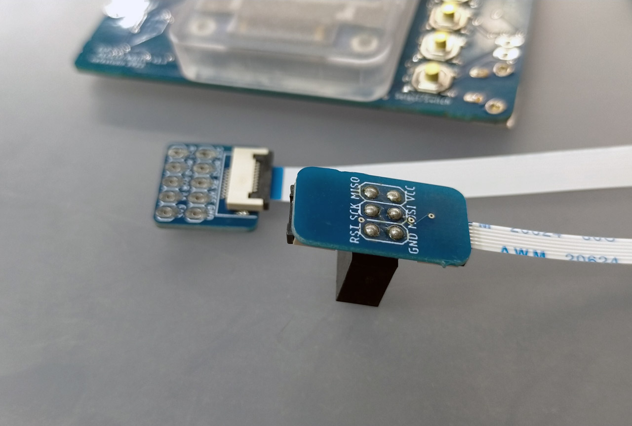
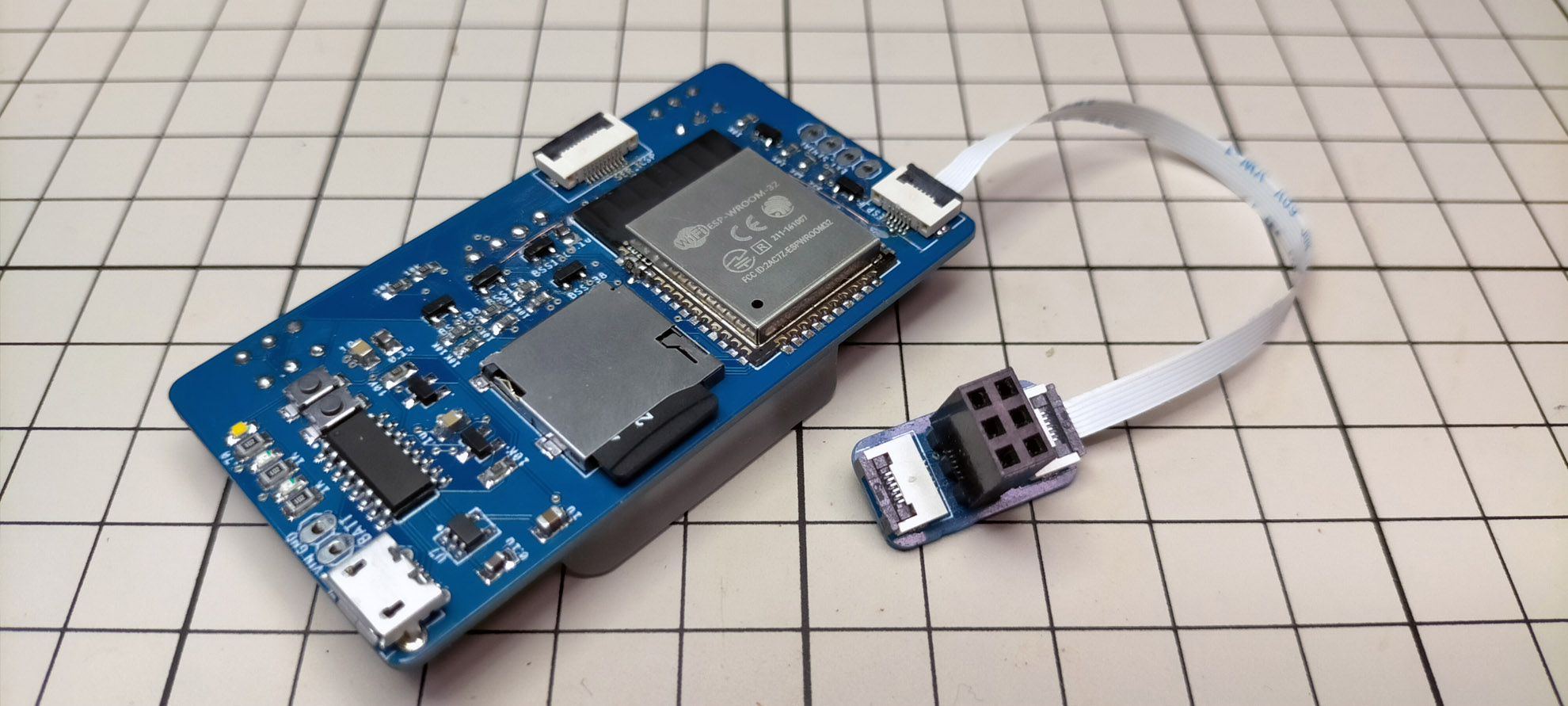
- ICSP pin connector (with 6 pin female connector)
- 10pin general purpose connector
For ICSP 6 pin connector, cut leg to favorite length and solder to board.
Lift up to open black cover for flat cable connector.
Preperation
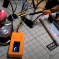
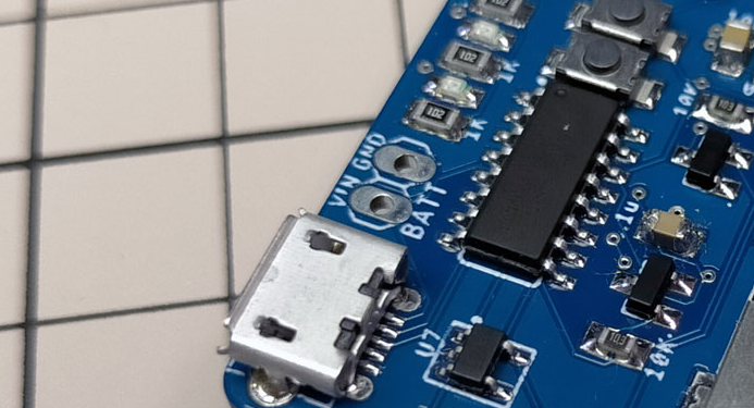
Before connection to target board, make sure voltage switch is in correct position. If connected to 3.3V chip with 5V output, it may brake the chip.
Power can be supplied from USB or Batt pin to tool, then to target board, or supply from target board to tool. V+ can be disconnected for isolated power supply for each.
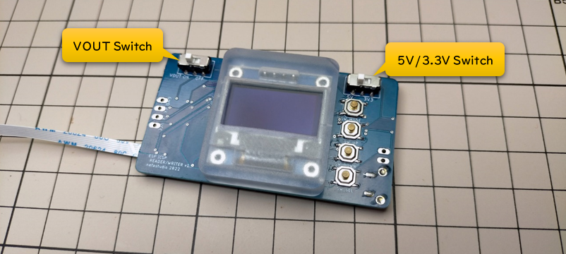
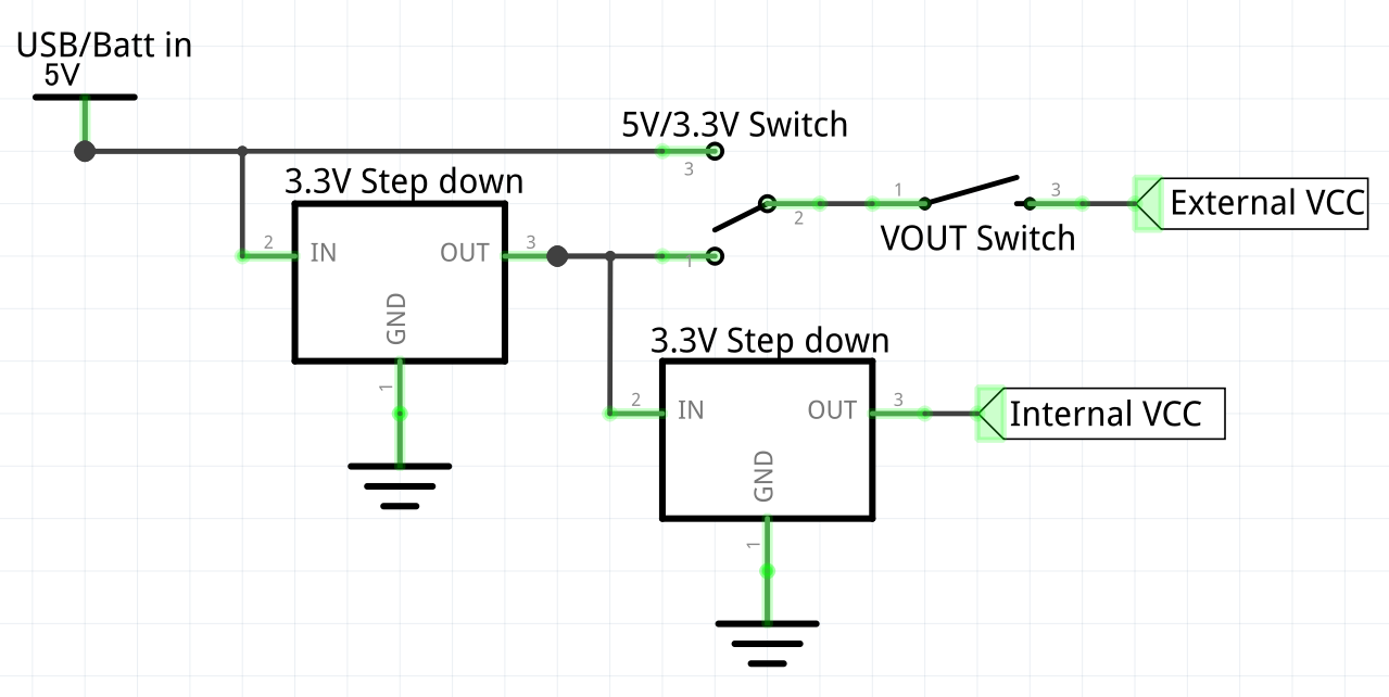
Below is simplified schematic for power circuit. VOUT switch will connect / disconnect tool power to target board.
Switching to 5V will connect USB / Batt pin to target board directly. 3.3V will supply 3.3V stepped down from USB / batt pin. Switch to 3.3V when getting 3.3V power supply from target board to tool.
3.3V step down converter is cascaded to protect tool from braking if switch is set to 3.3V and 5V power is fed from target board by mistake.
Batt pin near USB is connected to USB 5V/GND. Feeding 5V to this pin will also work. Since tool works with 3.3V, you can use 3.7V lipo battery for power, but in this case, 3.7V will be max output to target board.
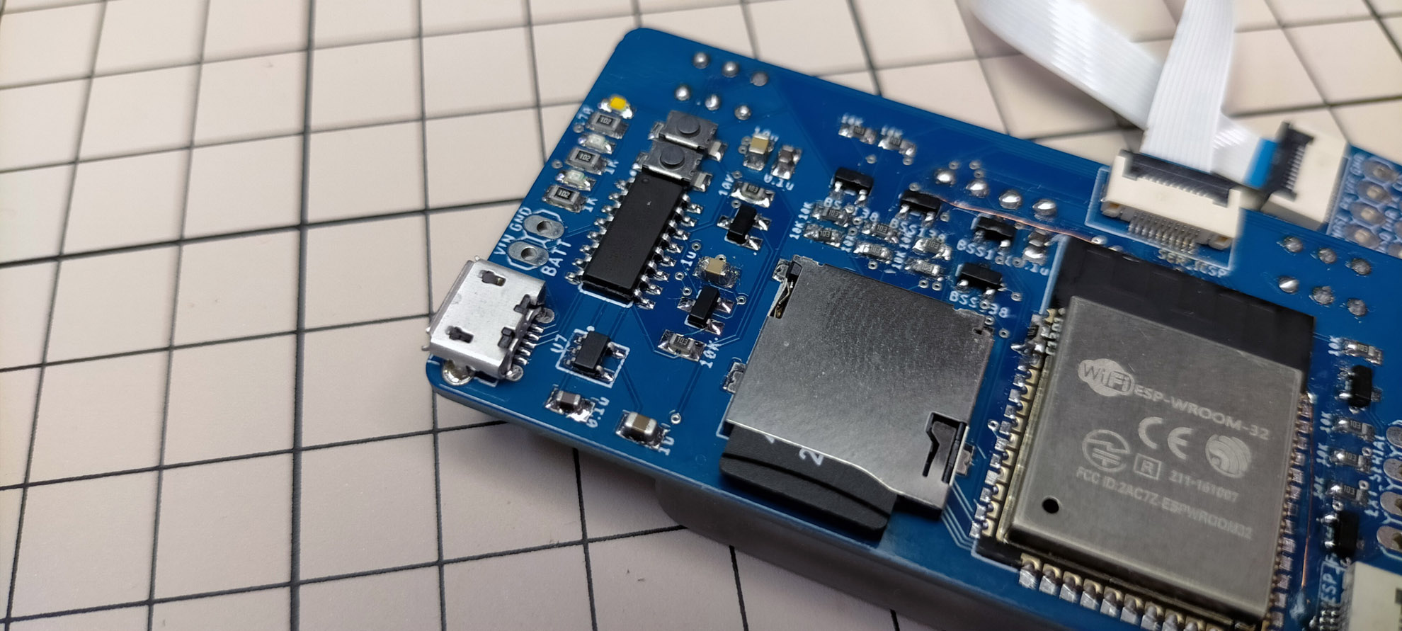
Insert microSD to slot. Large sized memory card is not supported; recommended to use 2 – 8GB FAT / FAT32 formatted microSD card. You can use tool without microSD with limited function.
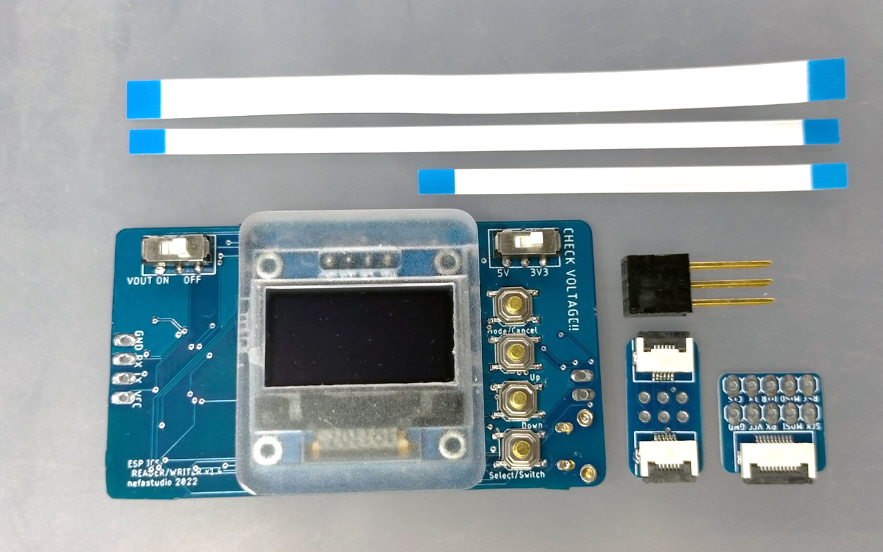
Connection
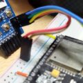
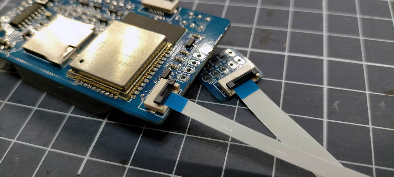
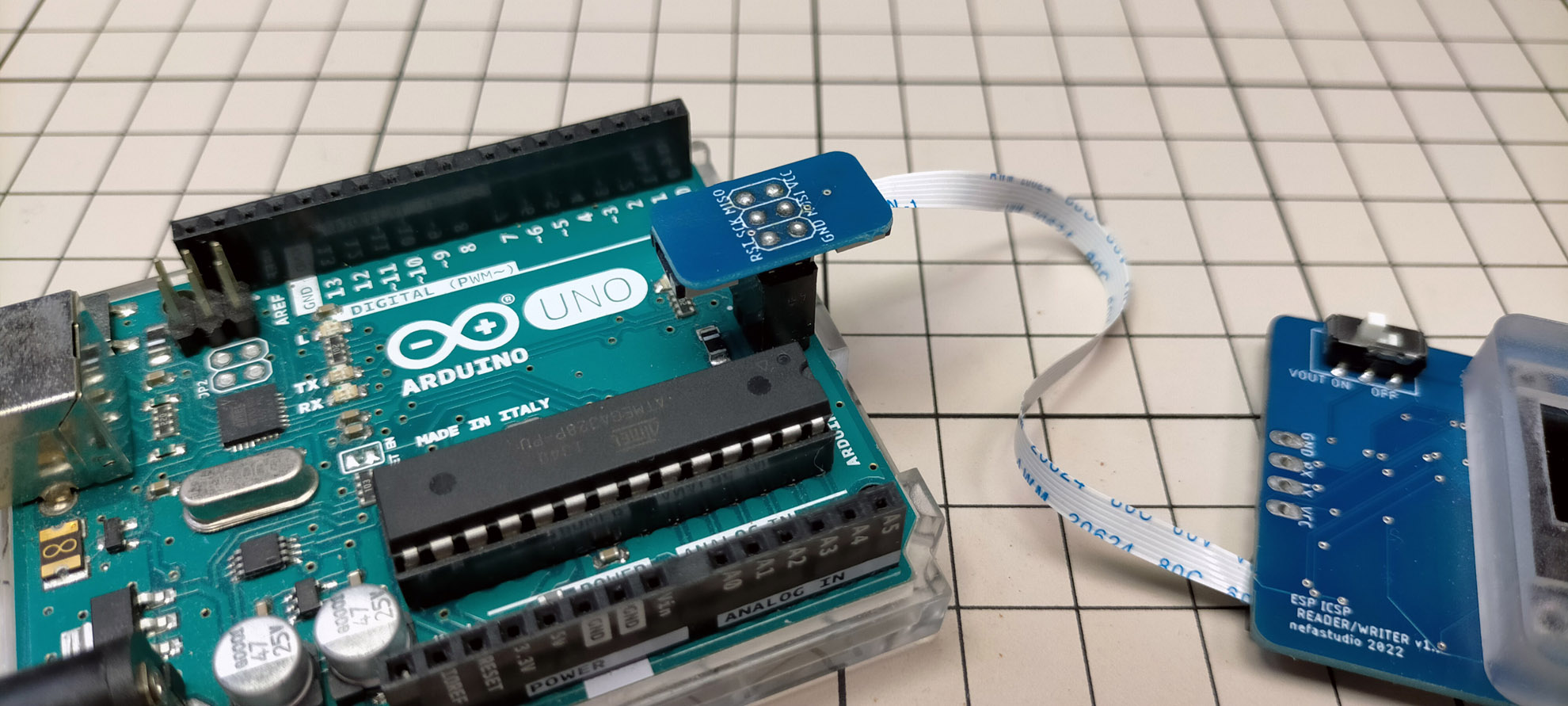
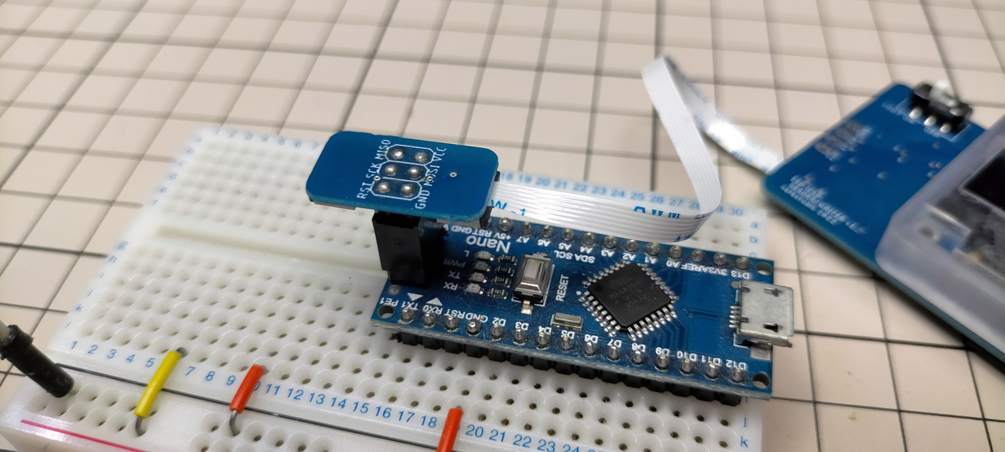
When burning bootloader, hex data, write/read Fuse, or write/read EEPROM, connect with ICSP. Pins used for ICSP is D11 – D13 (MOSI / MISO / SCK) for Arduino UNO. Disconnect any external device if connected to those pins or communication may fail.
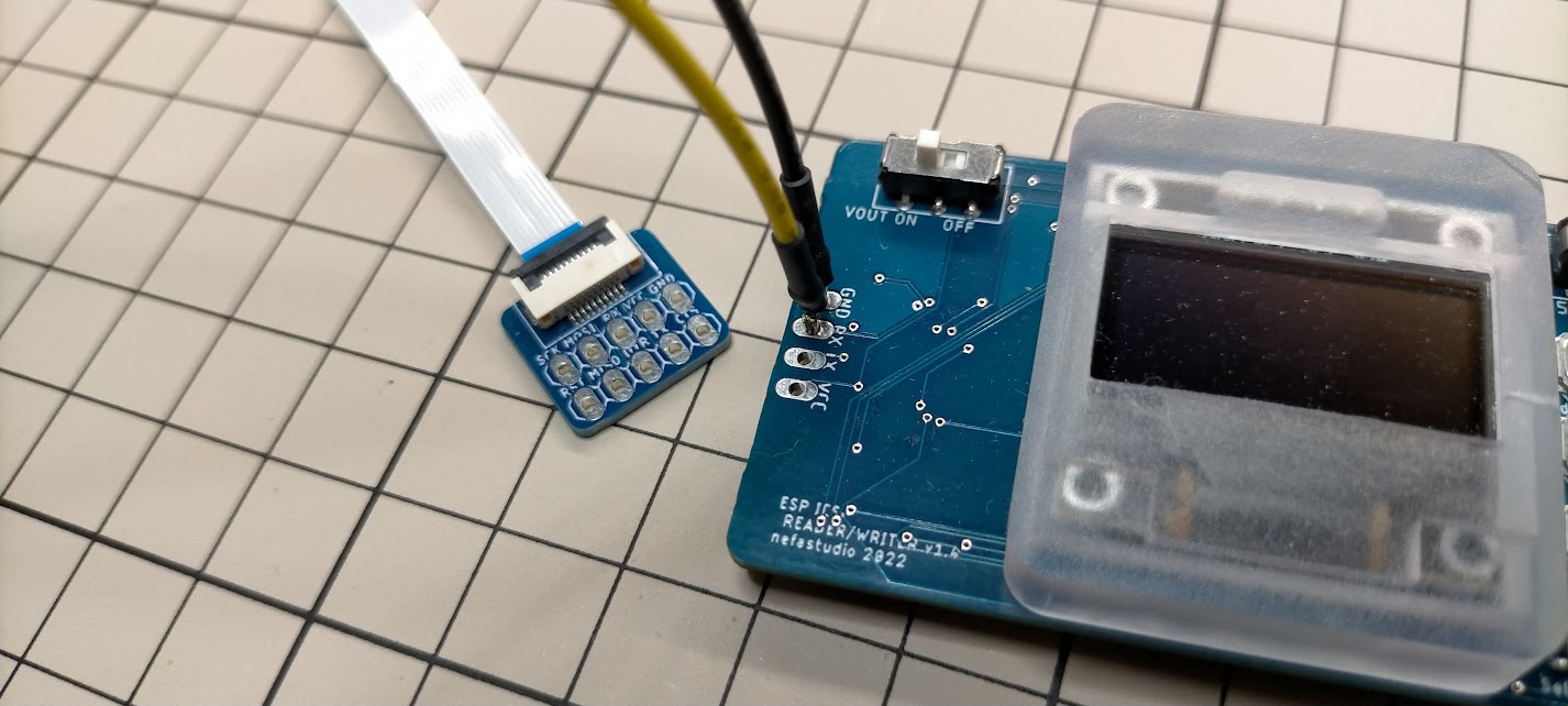
Connect flat cable to connector at back side of the tool. Connect 6 pin adapter to other end of flat cable. Adapter has flat cable connector on both side for you to choose favorite direction.
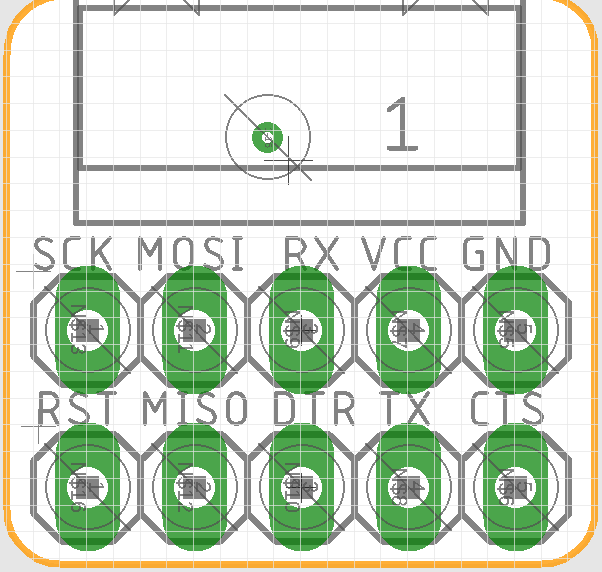
Check pin name printed at 6 pin adapter board, and be careful to connect to correct ICSP pins. For Arduino UNO, GND / MOSI / VCC is outside, and flipped for Arduino Nano.
10 pin flat cable connector also has ICSP pin and RX/TX pins. ICSP on 10 pin connector can also be used.
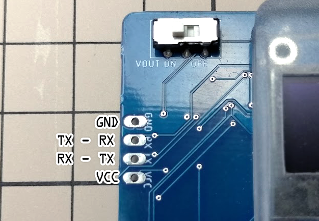
Pin assign for connector is as follows. (Pin name for target side; RX is actually TX for tool)
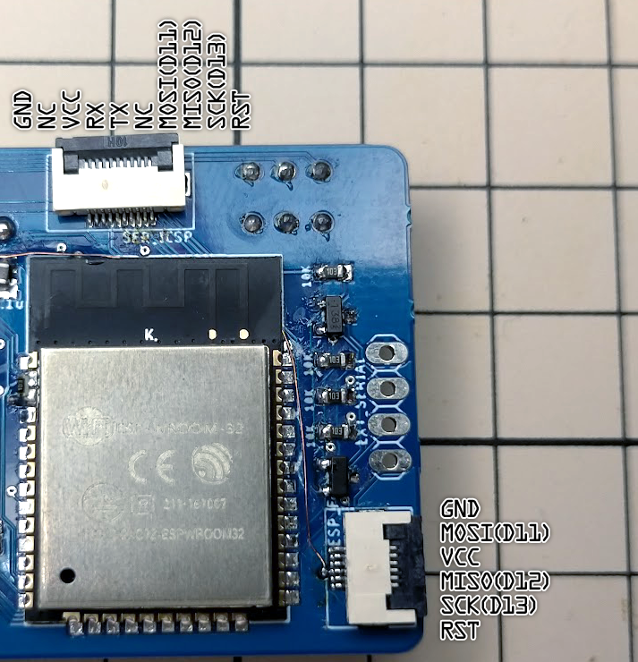
To use serial monitor, use TX/RX line in 10 pin connector or use pin at left side of the tool. RX / GND is least needed connection for serial monitoring.
Below is pin assign for general purpose 10 pin connector.
Boot
Tool does not have power switch, it will boot when power is supplied.
If tool seems to continuously rebooting, power supply may not be enough. In such case, use other power supply or change tool setting for low power consumption.
There are some way to lower tool power consumption.
- Remove microSD card (if not used)
- Disable WiFi (WiFi consumes power)
- Lower CPU clock
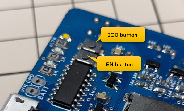
When powering on tool, holding down button will change mode. Hold down button while powering, or hold down button and press EN button to reboot.
- Hold Up button during boot : Clear WiFi connection seting.
- Hold Down button during boot : Disable WiFi.
- Hold Mode button during boot : Set CPU to 160MHz.
Basics
Button assign is as follows.
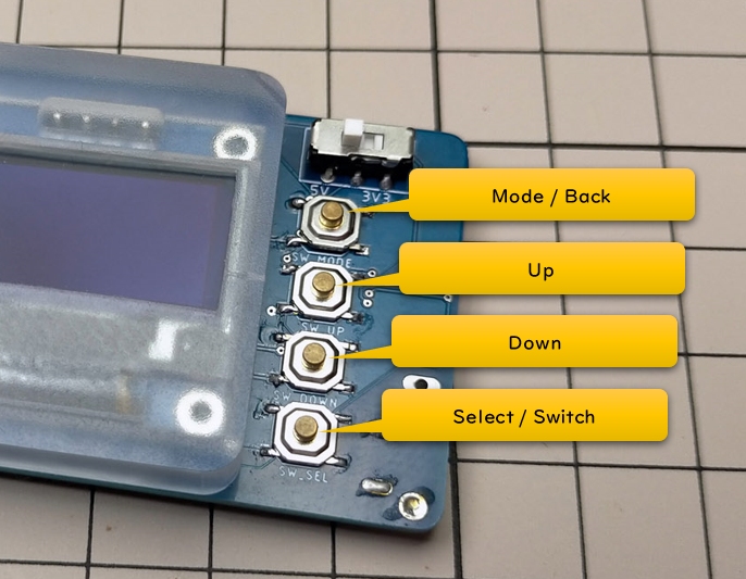
Pressing mode button will loop the mode.
- File
- Bootloader/Fuse
- USB / WiFi ISP
- Serial monitor
- EEPROM
- Web server
- Configuration
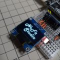
Screen display shows following info.
Left-top : current mode
Right-top : Time / WiFi antenna
When WiFi is configured and connected to internet, time is shown when synced with NTP server.
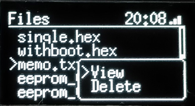
File
Shows file in microSD.
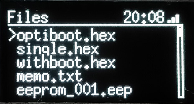
Up / down button to select file, and select button for file action. Action depends on file type. All file can be deleted.
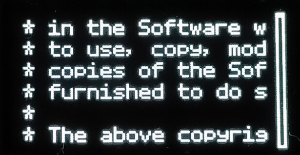
Text file (e.g. serial log)
txt file can be viewed (max 4096 lines). No horizontal scrolls, but pressing Select/Switch button will switch word wrap on / off.
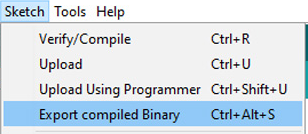
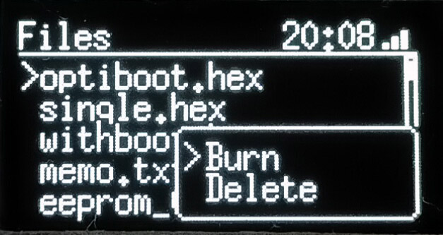
hex file
Writes hex file to Arduino connected with ICSP. Hex file can be created by selecting Export compiled Binary in Sketch menu.
Select file and select Burn from menu.
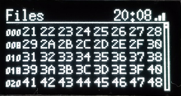
eep file
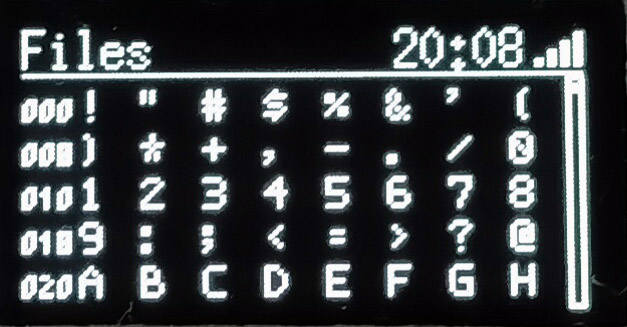
When EEPROM data is saved to microSD with EEPROM mode, data is saved with eep extension (plain binary format). View will show data, Burn will write to ICSP connected Arduino.
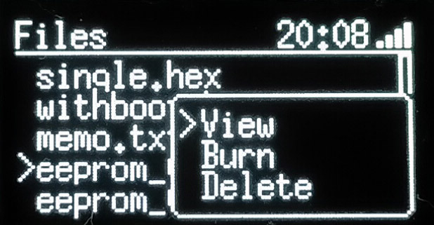
Pressing Select/Switch button switches between HEX and ASCII format.
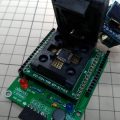
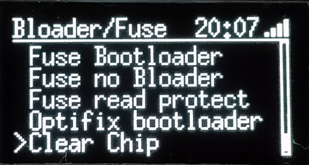
Bootloader/Fuse
Sets Fuse or write bootloader. Note that setting Fuse or bootloader may clear sketch in chip.
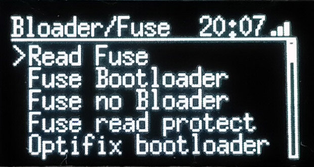
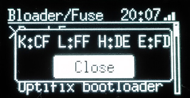
Read Fuse
Reads current Fuse setting. K is Lock, L is Low, H is High, E is Extended bit.
Fuse Bootloader
Sets fuse to use Bootloader.
Fuse no Bootloader
Sets fuse to not using Bootloader. Setting this fuse and burning sketch without bootloader code will instantly run sketch at bootup, which will make Arduino boot bit faster. However, you won’t be able to use normal procedure (i.e. from Arduino IDE) to overwrite new sketch data.
Fuse read protect
Read protects sketch data in chip.
Optifix bootloader
Burns Optifix bootloader.
Clear Chip
Clears chip data.
USB / WiFi ISP
Arduino as ISP mode, use avrdude via USB or WiFi.
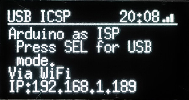
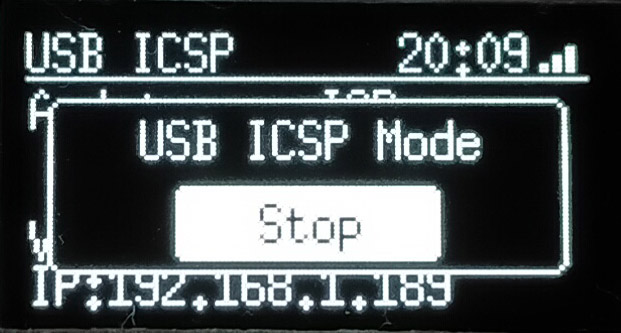
Press Select button to start USB mode. Connect target with ICSP and rest is same as Arduino as ISP usage.
If not in USB mode, it can be connected via WiFi (if WiFi connection is configured). avrdude over WiFi is unstable or causes error, and need some modification for using. You can get modified version of avrdude below.
Modified version is still unstable, and may fail occasionally. Try couple times and may recover.
Serial monitor
Simple serial monitor for viewing in text, graph, and save to file.
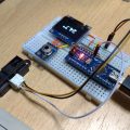
Use serial pin at left side of tool, or use serial pin in 10 pin connector. Test wire TTW-200 from Sunyhayato is useful as header can be plugged in to through-hole.
Since receive signal is only used, GND and RX (TX for target) connection is needed. Level converter is included in all signal lines.
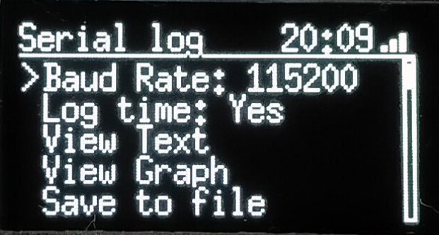
Baud Rate:9600 / 38400 / 78800 / 115200
Log time:records time at beginning of line (time in ms since tool powered)
You can select Serial2 or IO12/14 in Port setting, but ESP32 SoftwareSerial is not working well at this time. Using IO12/14 for serial monitor is useless right now.
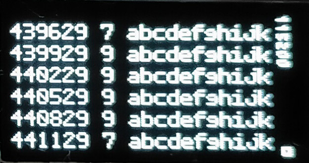
View Text
Simple text serial monitoring. No buffering or horizontal scrolling. Select/Switch button switches between word wrap on / off.
View text can be used while saving log to microSD.
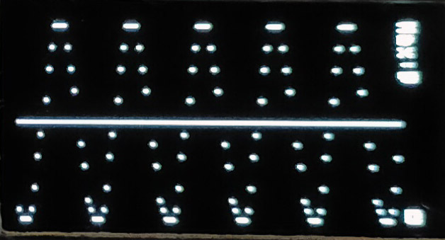
View Graph
Simple graph serial monitoring. Converts text to numeric value per line, and shows in graph. Graph is 0 at center and range is automatically adjusted to show max value since monitoring started. Right top shows current max value.
View graph can be used while saving log to microSD.
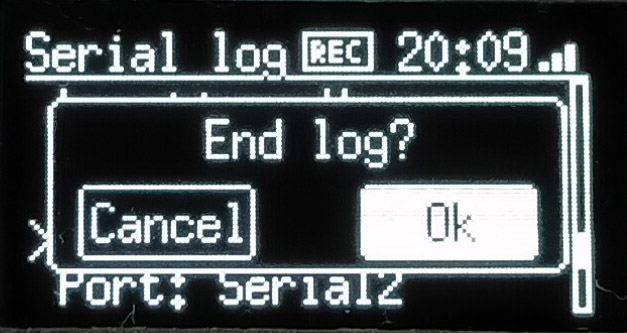
Save to file
Saves serial monitor log to microSD in text format. [REC] is shown at top of screen while recording. Select Save to file again, or press mode button to end logging.
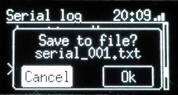
Saved log file can be viewed from file mode.
EEPROM
Can read and view / write / clear 1024 byte EEPROM data.
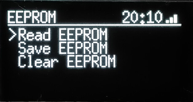
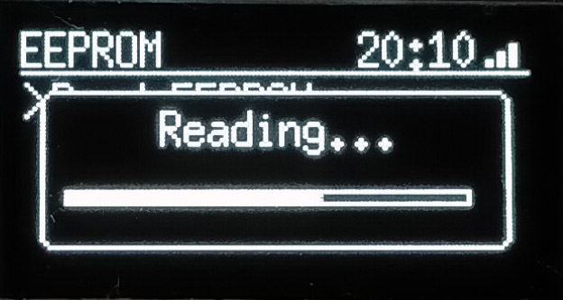
Read EEPROM
Read and show EEPROM data. Pressing Select/Switch button switches HEX / ASCII mode.
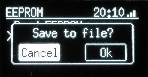
Save EEPROM
Saves EEPROM data to microSD in plain binary format. Can view contents of data or write saved data to chip from file mode.
Clear EEPROM
Clear EEPROM with 0.
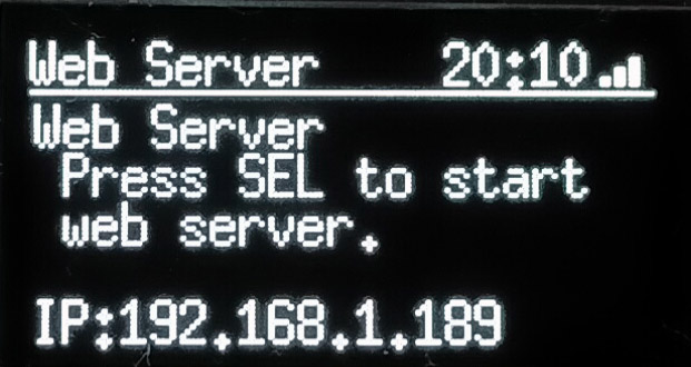
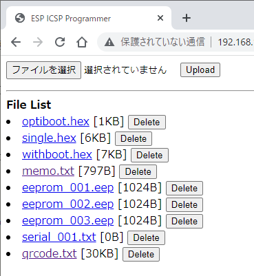
Web server
Works as simple Web server to transfer files in microSD. Press Select button to start / stop Web server.
QR code shows when Web server is running. Use QR code scanner in smartphone for simple connection.
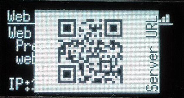
File list shown when accessed from browser. Click filename to download file, press delete to delete file, select file and Upload to transfer file to microSD.
Config
Configures WiFi setting.
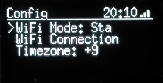
WiFi Mode
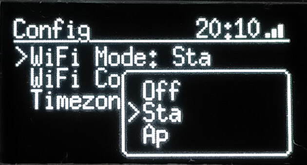
Changes WiFi mode. If there’s access point for WiFi connection, use station mode. When connected to internet, time is synced via NTP server (used for timestamp when saving file to microSD).
Set to AP mode to make tool run as access point. This will connect PC or smartphone to directly connect with tool. SSID will be “ESP_AVRISP_XXXX” and password will be “ESP_PASS_XXXX” (XXXX is unique per tool).
Set to Off to save tool power consumption.
WiFi Connection
Configures WiFi connection. Use smartphone and browser to configure.
Press Select button to enter WiFi configuration mode. Tool enters AP mode and waits for connection. QR code is shown, so you can read QR code for easy connection. Else, find SSID with ESP_AVRISP_XXXX (password is ESP_PASS_XXXX where XXXX is unique per tool).
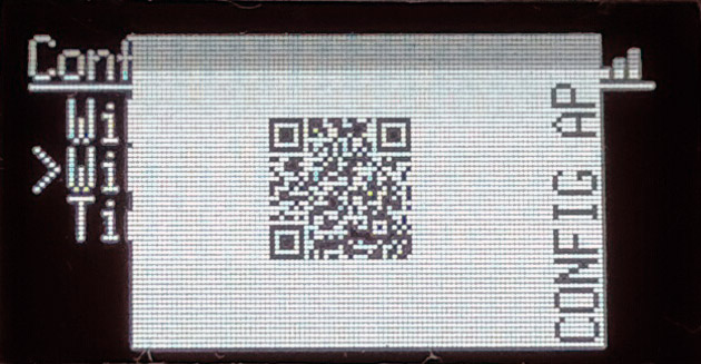
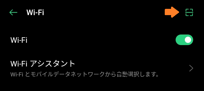
Depends on OS version for Android; scan icon is shown at top of WiFi connection screen. Tap scan icon and scan QR code will connect to tool.
When connected, browser may automatically launch. If not , open http://192.168.4.1 manually.
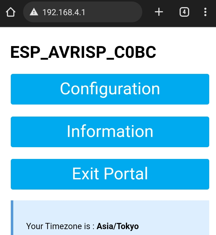
Top Configuration to select access point to connect.
Tap SSID automatically detected, or enter SSID manually, enter password and IP address, as needed (leave as 0.0.0.0 for DHCP). Tap Save to finish configuration.
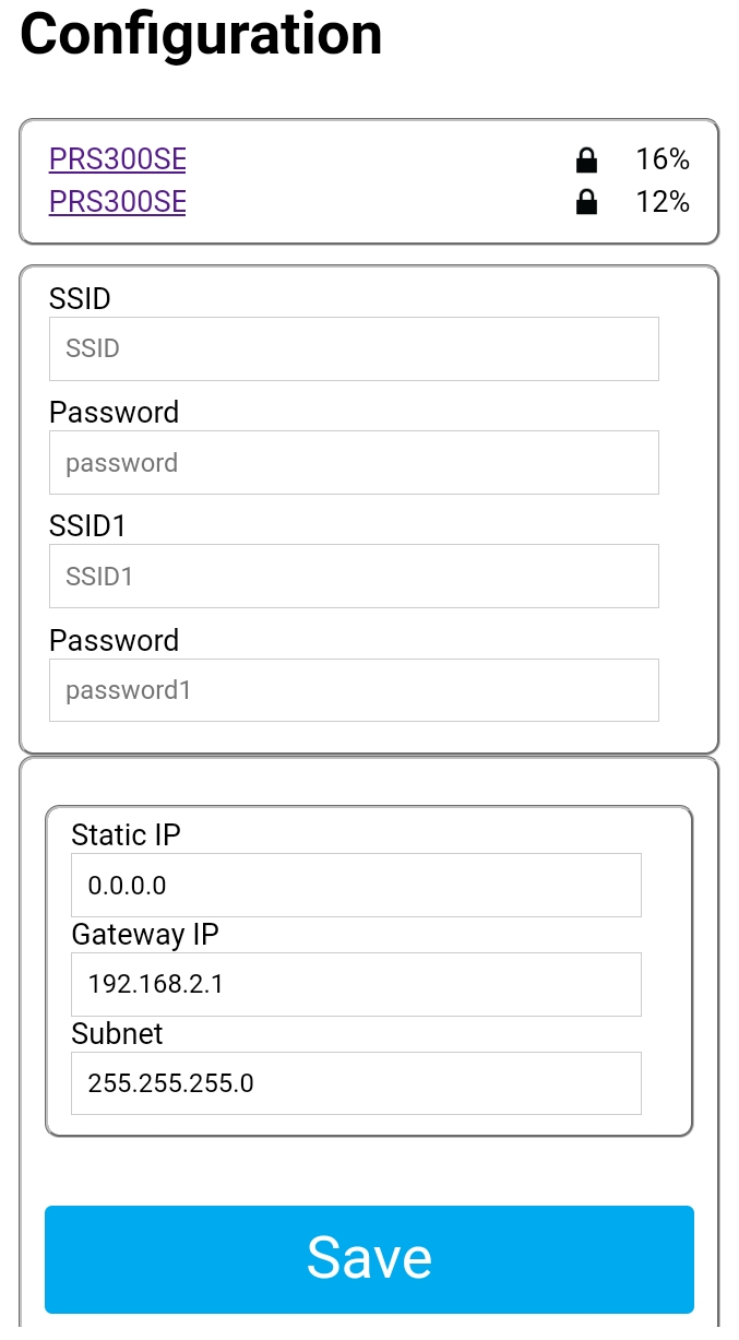
This will configure WiFi connection for tool.
Timezone
Set timezone. When connected to internet and time is synced with NTP server, time / date is used for timestamp when saving file to microSD.
Libraries
Software for this tool uses / based on / got idea from following libraries. Thank you for providing such a nice codes.
- Arduino as ISP(Arduino IDE sample sketch)
- optifix.pde Jan 2011 by Bill Westfield (“WestfW”)
- AVR In-System Programming over WiFi for ESP8266
https://github.com/lbernstone/ESP_AVRISP - QRcode
https://github.com/ricmoo/QRCode - ESP File Upload
https://github.com/G6EJD/ESP32-8266-File-Upload - u8g2
https://github.com/olikraus/u8g2 - ESP WiFimanager
https://github.com/khoih-prog/ESP_WiFiManager - SdFat
https://github.com/greiman/SdFat

This post is also available in: Japanese